Motorcycle Hacking
In 2017 I got a brand-new motorcycle, and it didn’t take long for me to start fiddling with it. As European laws are quite strict regarding modifications, I wanted to get data out of the ECU to an external embedded system to do fun things with it. This post is a technical description of my spelunking.
Talking to the ECU
First I wanted to be able to communicate with the ECU. This would allow me to log data to study how the bike behaves, and potentially dump the firmware. After some research, I found out my ECU uses a K-line protocol, possibly ISO 9141 or ISO 14230. I quickly found out some other people had already managed to communicate with ECUs like mine by reversing some accessories that are plugged to the diagnostics port. There are many gear indicators that are plug-and-play and can guess which gear is currently engaged by talking to the ECU. There was a person that tapped into the port to look at the messages the gear indicator was exchanging with the ECU. It turns out it may very well be true, that it doesn’t matter which crazy idea you have, somebody else probably already tried to do it. As expected, the interface operated at 10400 bauds (from the standard), but apparently the message content didn’t match the standards:
Initialization:
Pull line low for 70ms
Pull line high for 120ms
> FE 04 FF FF
Wait 200ms
> 72 05 00 F0 99
< 02 04 00 FA
Requests/responses:
> 72 07 72 11 00 14 F0
< 02 1A 72 11 00 00 00 18 00 62 57 EF 10 91 63 FF FF 77 00 00 00 80 63 1A 51 DA

> 72 07 72 D1 00 06 3E
< 02 0C 72 D1 00 03 00 00 00 00 00 AC
I unfortunately don’t have access to the ISO-14230-4 specification, so even if it was compliant, I wouldn’t be able to tell. The decoding would need to start from guesses. The collaborative work on these forums from more experienced people allowed most of the message to be decoded. One of the posters did a great job on building a circuit to communicate with the K-Line interface through a simple USB<->RS232 adapter. The schematics for the circuit seem to come from a russian forum, and had a few limitations, which I figured out only after building an equivalent circuit. The communication initialization requires a cycle of pulling down/up the K-line for specific time intervals, which isn’t simple to do with the RX/TX pins from the RS232 adapter (and not even possible for most RS232 chips). I added a third optocoupler that I can control using the RS232 DTR pin, allowing me to transmit the K-Line initialization sequence without any headaches. With all that, I built a first prototype for the circuit:
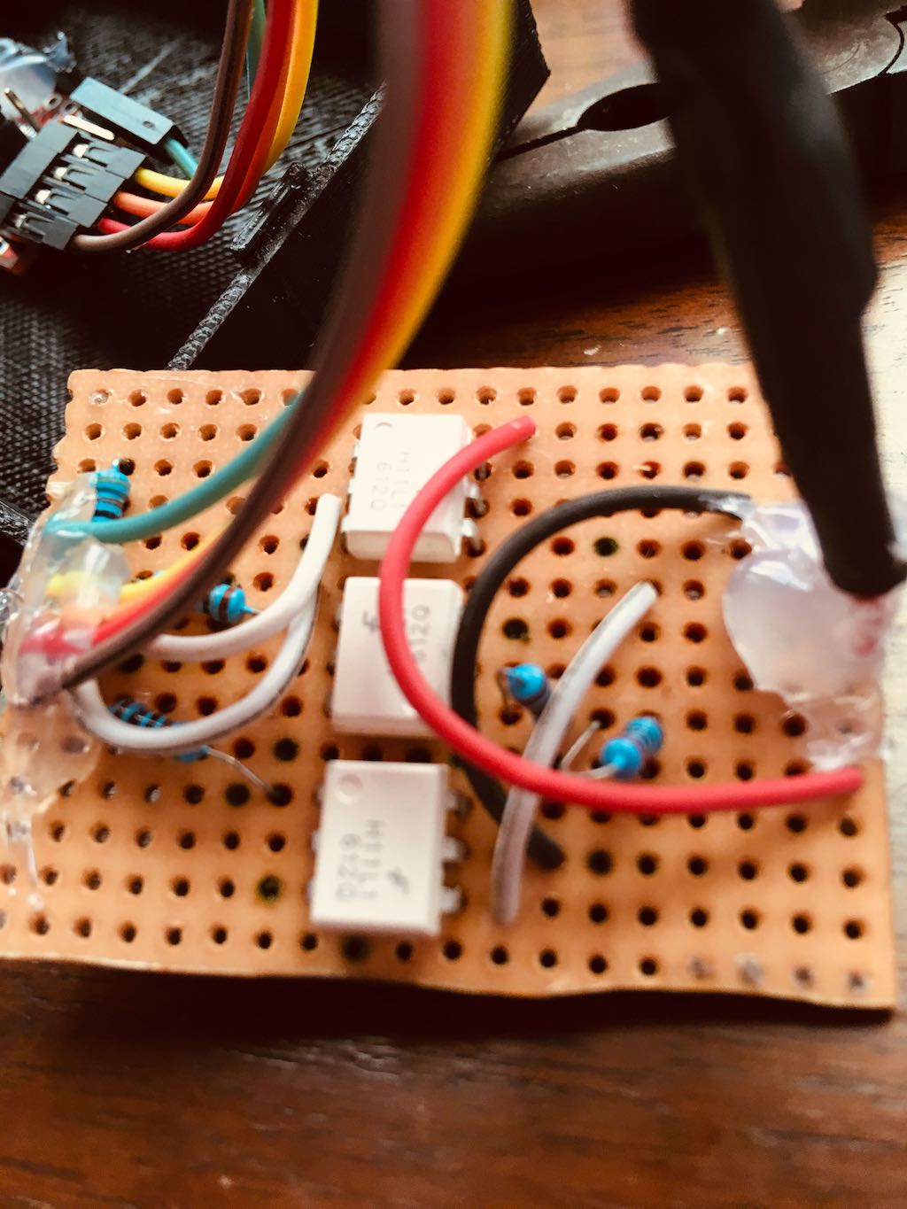
It’s just a prototype, I promise.
This circuit allowed me to use a simple Python program to communicate with the ECU. With that, I Immediately found a problem: the circuit was too sensitive to EM noise, and the messages would get corrupt all the time, forcing the program to reinitialize the connection. It was not easy for me to find the source of the problem, and required some time with a logic analizer to point out what was wrong. I found out the culprit was the 4N25 optocoupler, which isn’t the best choice when building a circuit that may be exposed to a lot of EM noise. Well, the culprit was me for choosing the wrong component, but you get it. I changed them for H11L1 ICs, as the schmitt-trigger circuit definitely more adapted for that. Circuit changed, problem solved. This is the circuit for the version I’m using:
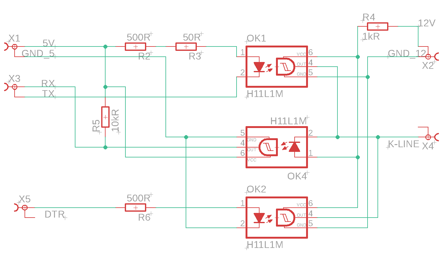
I know it’s ugly. But it was made with love.
Parsing the messages
It’s a guessing game: change it until you get to something that makes sense. Some things are absolutely obvious, like RPM and speed, but others not so much. Some members managed to decode most of the responses sent to the gear indicator:
   SRC,  LEN,  TGT, TABL, STRT,  LEN, CHK
> 0x72, 0x07, 0x72, 0xD1, 0x00, 0x05, 0x3F
   SRC,  LEN,  TGT, TABL, STRT, NEUT, ????, ????, ????,  ENG,  CHK
< 0x02, 0x0B, 0x72, 0xD1, 0x00, 0x00, 0x00, 0x00, 0x00, 0x01, 0xAF

   SRC,  LEN,  TGT, TABL, STRT,  LEN, CHK
> 0x72, 0x07, 0x72, 0x11, 0x00, 0x0E, 0xF6
   SRC,  LEN,  TGT, TABL, STRT, RPMH, RPML, TPSV, TPS%, ECTV, ECTC, IATV, IATC, MAPV, MAPP, ????, ????, BATV,  SPD,  CHK
< 0x02, 0x14, 0x72, 0x11, 0x00, 0x05, 0x5D, 0x19, 0x00, 0x2A, 0x7B, 0xAF, 0x36, 0x68, 0x45, 0xFF, 0xFF, 0x8B, 0x14, 0x18
It was also obvious that by changing the table address and read length, I could read more memory addresses. By trying to read many different bikes, a community table was built with some of the differences. Another member found documentation for an aftermarket display showing that probably the values after the speed were ignition advance and injection time. These two aren’t trivial to make sense of, and some members came up with different theories. I made some experiments myself and chose the method that gave the outputs that seem closer to reality.
It works fine, but it needs validation. With all that in hand, I decided to implement a custom display for my bike, displaying the data I was reading.
Display Box
I decided to attach a screen to the handlebars to display the data I’m interested in. For that, I came up with a few requirements for a first version:
- Screen should be easily detachable: This way I can remove it to protect it from the elements (sun/rain). If you never had to implement a weatherproof display that looks nice, I can tell you: there’s a painful learning curve (and I didn’t manage yet).
- Fast initialization: Screen should be available within seconds after turning the key.
- Non-destructive installation: Having it on the bike must not require the removal/modification of any original part.
With all that in mind, I came up with a project:
- Raspberry Pi for the graphics rendering power plus any need I may have on peripherals (GPS, IMU, Bluetooth, etc).
- Hyperpixel 4.0 for the screen (a big cheap screen with good resolution).
- Custom 3D printed case/support.
In the end, I got to something like this:
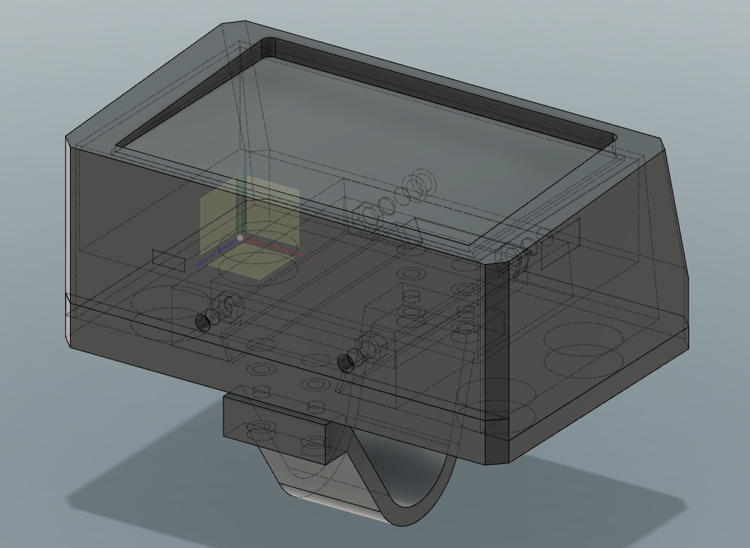
This way the display is attached to a Raspberry Pi and both can be removed easily (as a single unit), while the power supply and the K-Line<->RS232 circuit are installed permanently.
I modeled and printed the parts I needed for the installation, and managed to get all to fit properly. I used Fusion 360 for the modeling, but I still want to make some improvements before publishing them.
Software
I decided to separate the display from the ECU communication software. This way I have modular components that I can develop/test independently.
ECU Communication Software
As I was experimenting from the beginning using Python, I ended up writing the whole thing using Python. The amount of processing this application has to do is minimal, and it spends most of the execution time sleeping. I also added logging capabilities to it, so I can play with the data later. It is a very simple application with serial communication code and a few classes to abstract things.
Display Software
To allow fast initialization I decided to write an application that renders directly to the Raspberry’s framebuffer. This way I don’t need to start the whole X11 with a desktop environment before launching the application. I wrote the display software in C++ to make the most of the hardware, and used SDL2 to draw to the framebuffer directly through the videocore4 hardware using OpenGL ES 2.0. It takes around 7 seconds to boot, but that can be improved by creating a custom installation with Yocto or Buildroot.
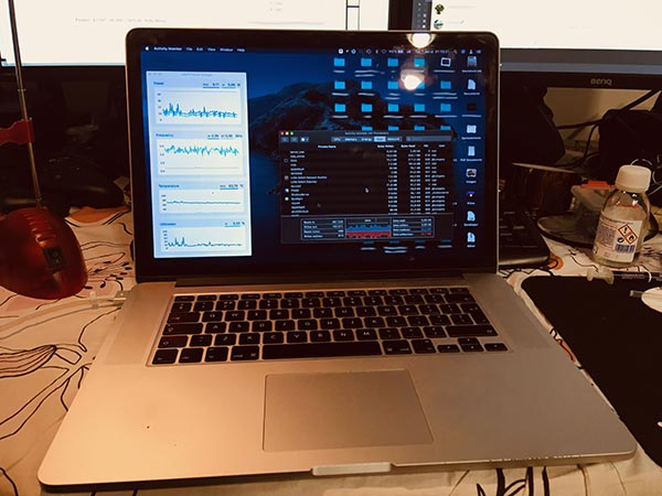
For development I obviously wanted to validate everything on my computer before trying anything on the Raspberry. To minimize headaches from switching between OpenGL and OpenGL ES, I used ANGLE to have an OpenGL ES 2.0 interface on my desktop. This way my whole code would be compliant with OpenGL ES 2.0 from the very beginning.
The application is very simple, and should work very well as a basic C++ / OpenGL / text rendering / network socket communication template. I made the base for it an open-source project, and called it Rockette.
Completed installation
A funny thing is that the OEM speedometer seems to disagree with the ECU speed value. I compared them to GPS speed measurements and the ECU speed matches almost perfectly with the GPS speed.
The whole system worked very well, but I’m still not sure the parsing of all elements is correct. To be sure, I would need access to the standards or to reverse engineer the ECU firmware, which I have not done yet.
Getting the binaries
I also have the original (unrestricted) ECU, so if I found a way to dump the firmware from both the restricted and understricted ECUs, I’d be able to compare them. But, how could I dump the firmware? I didn’t even need to figure that out, as I could find dumps for both the restricted and unrestricted ECUs on the internet. Thanks internet.
Reverse engineering
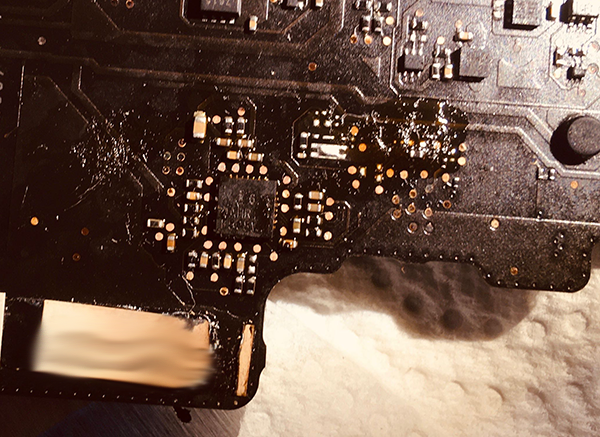
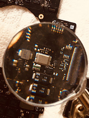
With the binaries in hand, I needed to know which instruction set they used, so I could reverse them. My ECUs seem to be plastic-molded and resin-filled (which is quite common for these things), and there doesn’t seem to be a non-destructive way to get them open to peek at the microcontroller. After hours searching the internet, I managed to find a random guy on a random forum that cracked open an ECU just like mine and posted photos of the board to get details on how to flash it. I didn’t have access to the full-resolution images, just the thumbnails, and I felt like this.
Fortunately, on his last post on this thread, he posted what I needed: The MCU had “Freescale 2M27V” written on it. The microcontroller is an MPC5604B! This microcontroller uses the e200z0 PowerPC instruction set with VLE support, but I can’t find a way to get a valid disassembler for it. Ghidra and other tools don’t seem to support this architecture, so please let me know if you know what I’m missing.
Injection Maps
Even without being able to reverse the binary, I was be able to extract the injection maps. I found very instructive tutorials on the internet on how to use a tool called WinOLS, and not only managed to extract many different injection maps, but also to compare the maps from the restricted and non-restricted binaries.
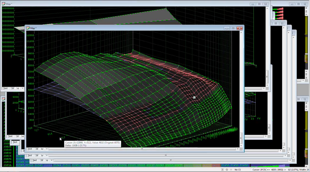
Comparing the ECU maps between the European A2 restricted and unrestricted versions
Matching data with maps
The parsing still needs validation for some values. As I collect logs I’ll compare the logged data with the maps I found.
Similar projects
https://github.com/atoid/Dash https://github.com/atoid/DashBle https://gonzos.net/projects/ctx-obd/ https://bitbucket.org/enly1/hondagearindicator/src/master/